"Restoration projects are always a bit special, and that definitely applies to the restoration of a shaft trestle at the be-MINE site in Beringen," Alexander Willems says. “Be-MINE is the name of the repurposing project for the former Beringen coal mine that was closed in 1989. As part of that project, a large part of the site has been redeveloped into an "experience site". For example, an old mine terrace now serves as an “adventure mountain”, and the ventilation building located in the former power station has been converted into a climbing hall.
Our assignment revolved around two questions
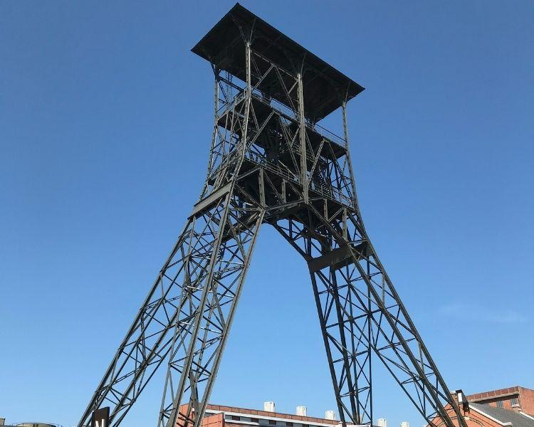
Two shaft trestles are still present at the be-MINE site. A shaft trestle is a structure built on top of a mine shaft to enable the transport of miners, materials and coal. It typically consists of two elements: the supporting structure and the elevator shaft.
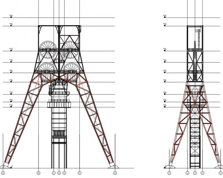
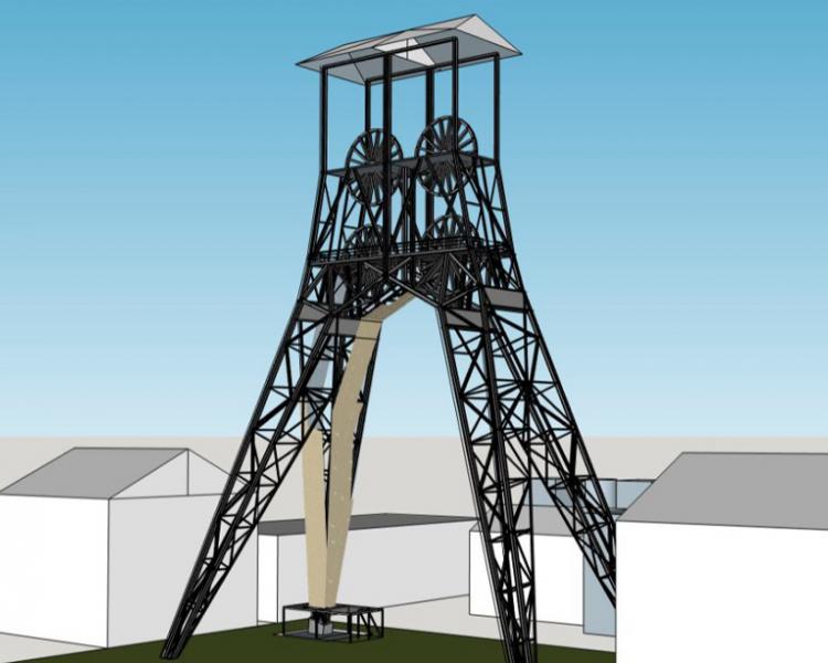
The supporting structure of shaft trestle I next to the former power plant is a freestanding frame with two pairs of angled legs and a cabin on top. The shaft’s legs do not only bear the weight of the cable wheels installed in the cabin but also have to resist the horizontal component of the cable pulling forces.
Before the restoration project kicked off, the elevator shaft was still present in between the shaft trestle’s legs. That elevator shaft was a steel frame extending, as it were, the mine shaft above ground level and guiding the elevator cage, providing several vital safety mechanisms as well as the stairways needed for maintenance purposes. Although the elevator shaft was connected to the shaft trestle’s supporting structure, it most likely had no load-bearing function.
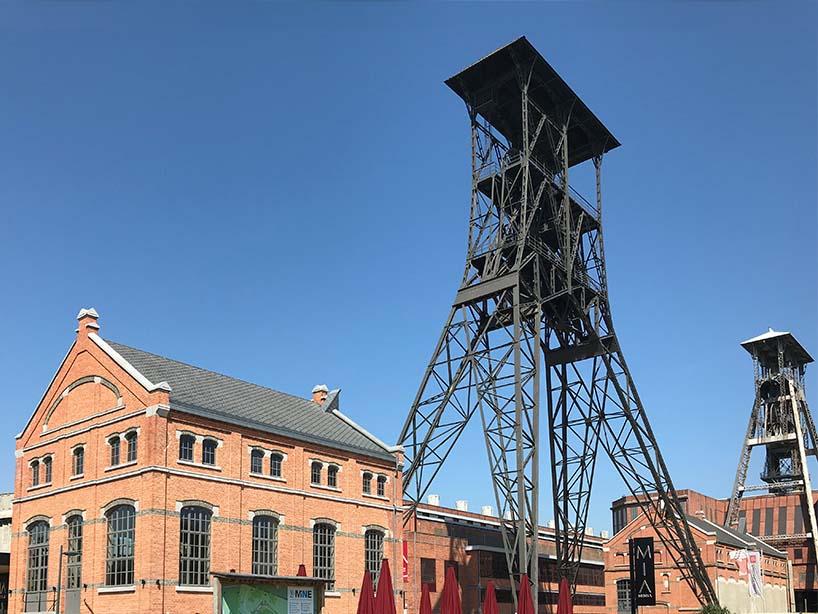
View of shaft trestle I at the be-MINE site in Beringen, before the start of the restoration (© Koplamp Architecten)
In the scope of this restoration project, we were asked the following questions:
- How much does the elevator shaft contribute to the overall stability of the shaft trestle? Can the elevator shaft be removed without compromising shaft trestle stability? And what about the stability during restoration?
- Besides, is it possible to install an outdoor climbing wall on one of the shaft legs, as an extension of the existing climbing hall in the adjacent power plant?
Can the shaft trestle remain upright once the elevator shaft has been taken down?
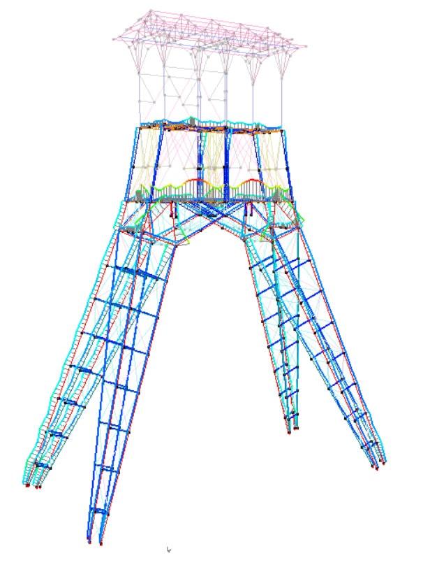
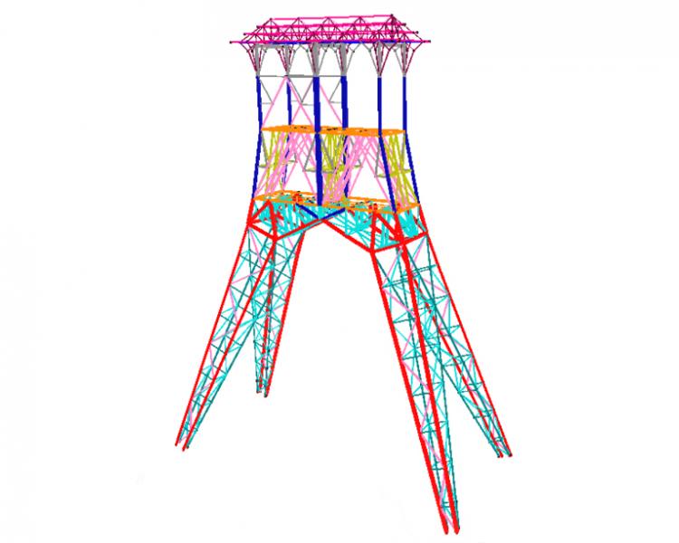
To evaluate whether the supporting structure of shaft trestle I can remain upright once the elevator shaft has been taken down, we built a 3D structural analysis model using the BuildSoft Diamonds software. In addition to the permanent loads (which include the weight of the cable wheels and the cabin’s steel floor), the wind loads on this freestanding structure play an important role. Obviously, the heavy loads acting on the supporting structure during the operation of the mine shaft were no longer present. It therefore seemed plausible that the elevator shaft could be demolished without problems, albeit that this needed confirmation through a structural analysis using the Diamonds software.
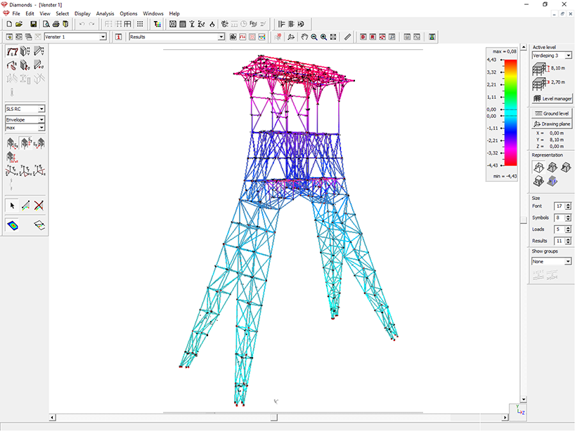
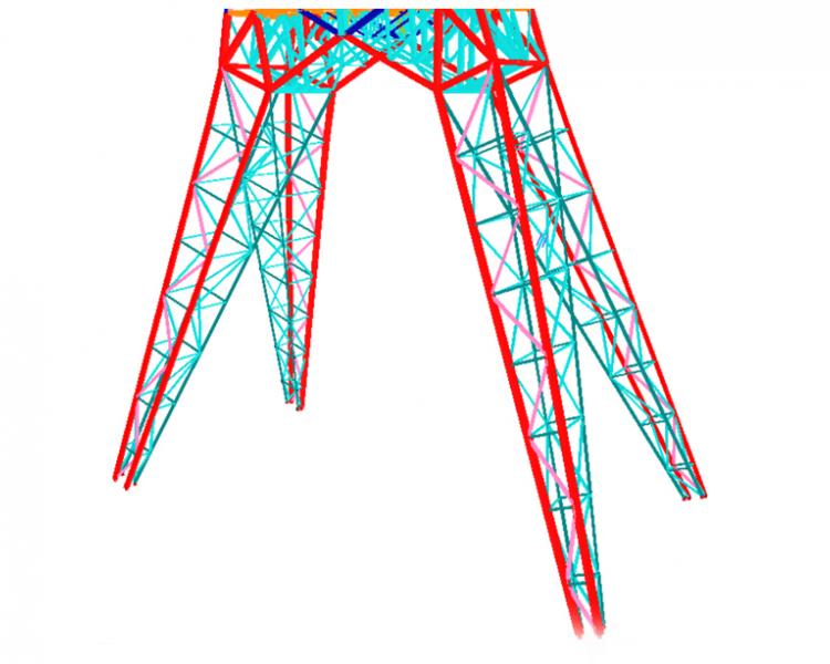
Diamonds structural analysis model of the supporting structure of shaft trestle I at the be-MINE site in Beringen
The restored shaft trestle I at the be-MINE site in Beringen
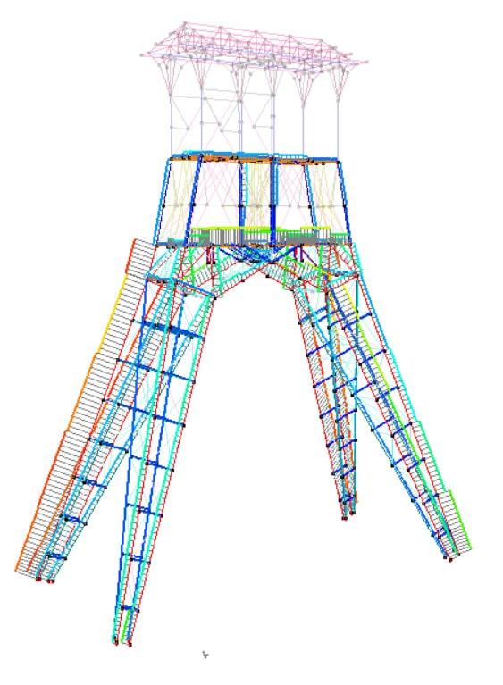
These analyses delivered all results that were required to perform the resistance and stability checks for all steel members of the supporting structure. I should mention that almost all steel members were defined to have composite UPN cross-sections (in case of the primary vertical members and the primary beams and diagonals) or composite corner sections (in case of the secondary beams and diagonals).
The resistance and stability checks confirmed that the shaft trestle could effectively remain upright without the elevator shaft being present. The primary vertical members as well as the secondary vertical members of the shaft trestle legs proved to be the most heavily loaded, up to 90% of their load-carrying capacity.
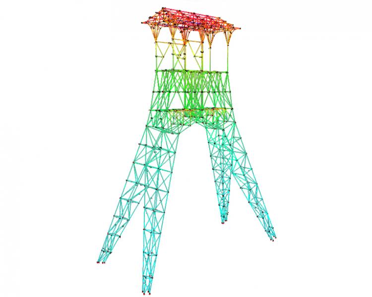
Results of cross-section resistance check for the supporting structure of shaft trestle I, calculated with Diamonds
Results of member stability checks for the supporting structure of shaft trestle I, calculated with Diamonds
On the other hand, due attention had to be paid to the shaft trestle’s horizontal deformations induced by wind loads. The maximum deflection at the top of the supporting structure (at the height of 56 meters above ground level) proved to be within the permissible values specified by the design standard. But what makes the calculation model interesting is the visualization of the deformations. After all, this shows that the horizontal deflection is most important in the relatively flexible upper part of the shaft trestle. That, in turn, confirms that horizontal deflections can best be reduced by means of diagonal stiffeners at the top.
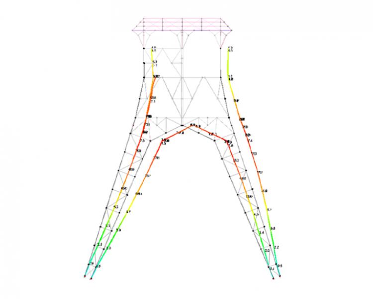
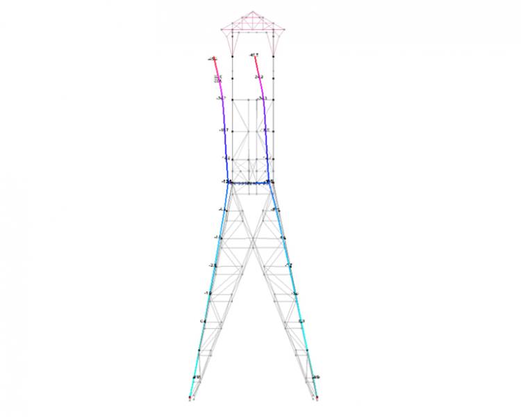
The horizontal deflection of shaft trestle I’s supporting structure due to wind loads, as calculated with Diamonds
How to plan the restoration works?
In addition to performing a structural design analysis of the freestanding shaft trestle, we also used Diamonds to validate the progress of the restoration process. During the restoration, scaffolding was built around the shaft trestle’s supporting structure and locally protected with a tarpaulin where restoration was ongoing. The freestanding shaft trestle had to be capable of resisting the wind loads acting on the canvas.
That was validated through a series of Diamonds analyses in close consultation with the contractor of the restoration works. The purpose was to estimate the effects of wind loads as a function of how the restoration progress was planned. In this way, Diamonds was used to support the planning process, and to guarantee that the extra wind loads acting on the canvas didn’t pose any risk to the overall stability of the shaft trestle.
Is it possible to install an outdoor climbing wall on one of the shaft trestle’s legs?
In a final phase, a series of analyses were performed to investigate the overall stability of the freestanding shaft trestle due to additional wind loads induced by approximately 400 m2 of weather-resistant climbing panels installed on one of the shaft legs.
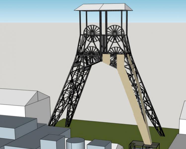
Visualization of the outdoor climbing wall on the south-western leg of shaft trestle I in Beringen (© Alpamayo)
Diamonds analysis model of shaft trestle I’s supporting structure in Beringen, including a detail view of the south-western leg clad with weather-resistant climbing panels
The presence of weather-resistant climbing panels over a relatively large height entails additional wind loads. However, taking into account the findings of previous structural analyses on the freestanding shaft trestle, it was expected that this would not have a substantial impact on the overall stability of the supporting structure.
The structural analyses with the 3D Diamonds model delivered full confirmation. The way we experience Diamonds’ user-friendliness is that it quite naturally complements our practice-oriented approach. After all, we have been using BuildSoft structural analysis software for almost a quarter of a century. Doesn't that speak for itself?